
Our last instalment covered the creation of the trucks’ tires. The next thing we made was the trucks’ frames. The trucks are mounted quite high on the display so the undercarriage will be quite visible. To keep things relatively simple, we used the same frame for both vehicles. We've built a few hotrods in the past, so we didn't have to do any research on the subject.
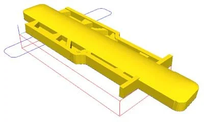
The vectors were created in EnRoute. The large rectangles going in both directions were used to create necessary bends in the frame.

The frame rails were simple flat reliefs 1" tall. The cross members were 0.9" tall so they would tuck under the main rails. The floor pan was 0.3" thick.
After these were built, we created a separate relief with the dome tool using the horizontal rectangle. We then selected the two cross members we wanted to curve upwards and then the big rectangular shape. By “merging highest” the crossmembers were instantly curved.
After this, iit was time to do the rear floor pan and the rear of the frame rails. We created a concave shape with the dome tool and line it up with the top of the frame rails. The frame rails were curved downwards using “merge lowest.” We then nudged the concave shape downwards until it lined up with the floor pan and repeated the merge lowest procedure.


At this point, we are almost done. We used the various vector shapes with the dome and bevel tools to create the different elements of the engine oil pan and the transmission and transfer case shapes. The rivets on the frame cross members was the finishing touch for this stage. And as simple as that, we had our trucks’ frames ready to tool-path and send to the CNC router.


We routed the frame from 1.5" thick 30 lb. Precision Board HDU.

We were delighted with the little frame of the truck when it came off the router. The detail was good and everything looked pretty much as we had imagined them.
Unfortunately, when we mocked the trucks up with the large wheels it looked kinda dinky. While the width longer good, it was definitely too short. So, it was time to make some adjustments and give it one more go on the router.
We measured things up again by holding the wheels against the frame, opened the frame file in EnRoute and stretched it out. The cross members were a little thicker than we originally designed but still looked good. As you've may have guessed, we tend to design as we go - by the seat of our pants and at a full run! We design by eye, so tape measures are generally used as a last resort. It definitely has it advantages, but sometimes (as in this case) we have to make adjustments as we go.
We tool-pathed our adjusted file and sent it on to the router. The rough pass was done in one pass with a 3/8" ballnose bit and a 50% overlap. And, we used a tapered 1/8" ballnose for the final pass, again all in one go, and with an 80% overlap.
